Building a Flight Computer from Scratch
This is the first post, hopefully in a series, about building a flight computer from scratch with embedded Rust. When I say from scratch, I really mean it: I’m designing the hardware, the software, the airframe, and the design requirements entirely from scratch.
I have made some progress which is summarized later in this article.
Quick bullets:
Hardware
- custom PCB
- sensors: gyro, compass, pressure sensor
- mcu: STM32F401 (64K of SRAM)
- radio: FrSky transmitter and 915MHz for telemetry
- USB 2.0 and UART breakouts
- option for GPS & differential pressure sensor
Airframe (still TBD):
- glider airframe, optimized for flight time
- power: probably 2S or 3S
- wingspan: ~6m
- weight: ~1kg
Software:
- embedded (no_std) Rust
- stm32f4xx-hal. 1 custom driver so far.
- RTIC for RTOS. Maybe a custom RTOS
- Companion GUI application for configuration and data download, also Rust
I am planning for this to be a glider airframe, optimized for long-term loitering. I think eventually I want to put a camera up there and experiment with computer vision, but that has to come in a year when I have the flight computer working. The reason for a glider is that it’s a combined hardware + software challenge and perhaps a bit different than what most people are doing with their RC airframes.
Why?
The real purpose of this project is to learn. I am focused on the difficult parts: embedded Rust (which after solid year I don’t feel is that difficult), control theory and aerodynamics, and hardware design. I am not too interested in airframe design. There are a few things that I am not trying to do:
- use off-the-shelf stuff (like pixhawk or ardupilot) or a pre-manufactured airframe
- develop my own airframe. I’m planning to use an already existing design from the youtube channel Experimental Airlines.
- build a super high performing aircraft or do anything super exotic (aside from maximize flight time)
- sell anything or start a business
- although I may sell at cost so other people can use it and give me feedback
Hardware: Current Progress
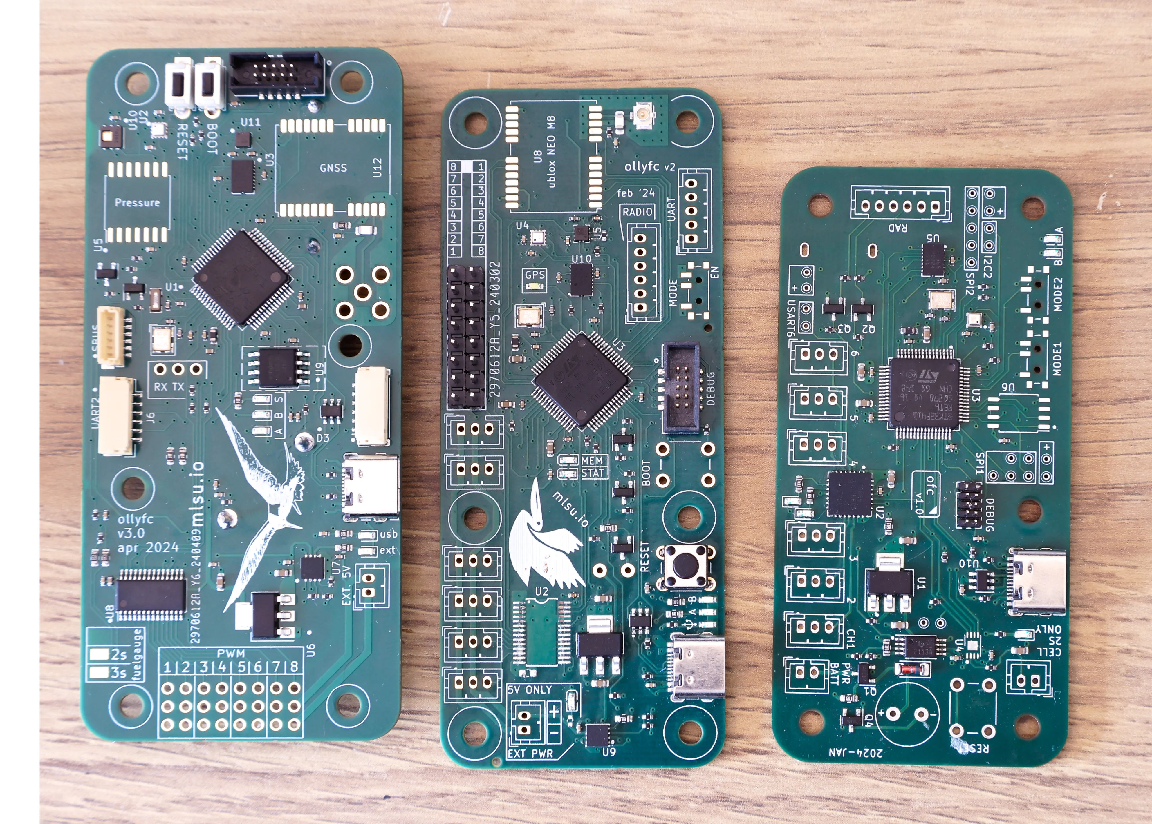
So far, I have produced 3 hardware prototypes.
V1 Hardware
The first version of the OllyFC flight computer was designed in late 2023. The units arrived from JLCPCB in January.
Unfortunately, the design had the boot0 pin floating. I’m not sure if this is a critical design flaw, but it is specifically pointed out by probe-rs as an issue that prevents debugging and flashing:
On STM32 series chips, check the state of the BOOT0 pin:
- If BOOT0 is HIGH or floating, the core will run from internal bootloader instead of flashed firmware.
- BOOT0 should be pulled LOW for SWD programming, however even if it is HIGH or floating, programming may appear to succeed but firmware will not properly run.
You can see the intended layout.
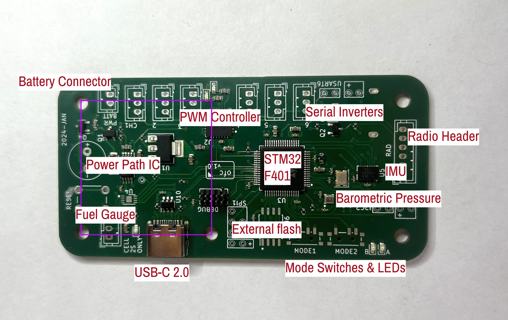
The purple rectangle is sized 30.5mm x 30.5mm, which is the standard size for a drone power distribution board. These are cheap and do the difficult electrical work of converting the high voltage battery power to a stable 5V.
Unfortunately, this board doesn’t work. Lesson learned?
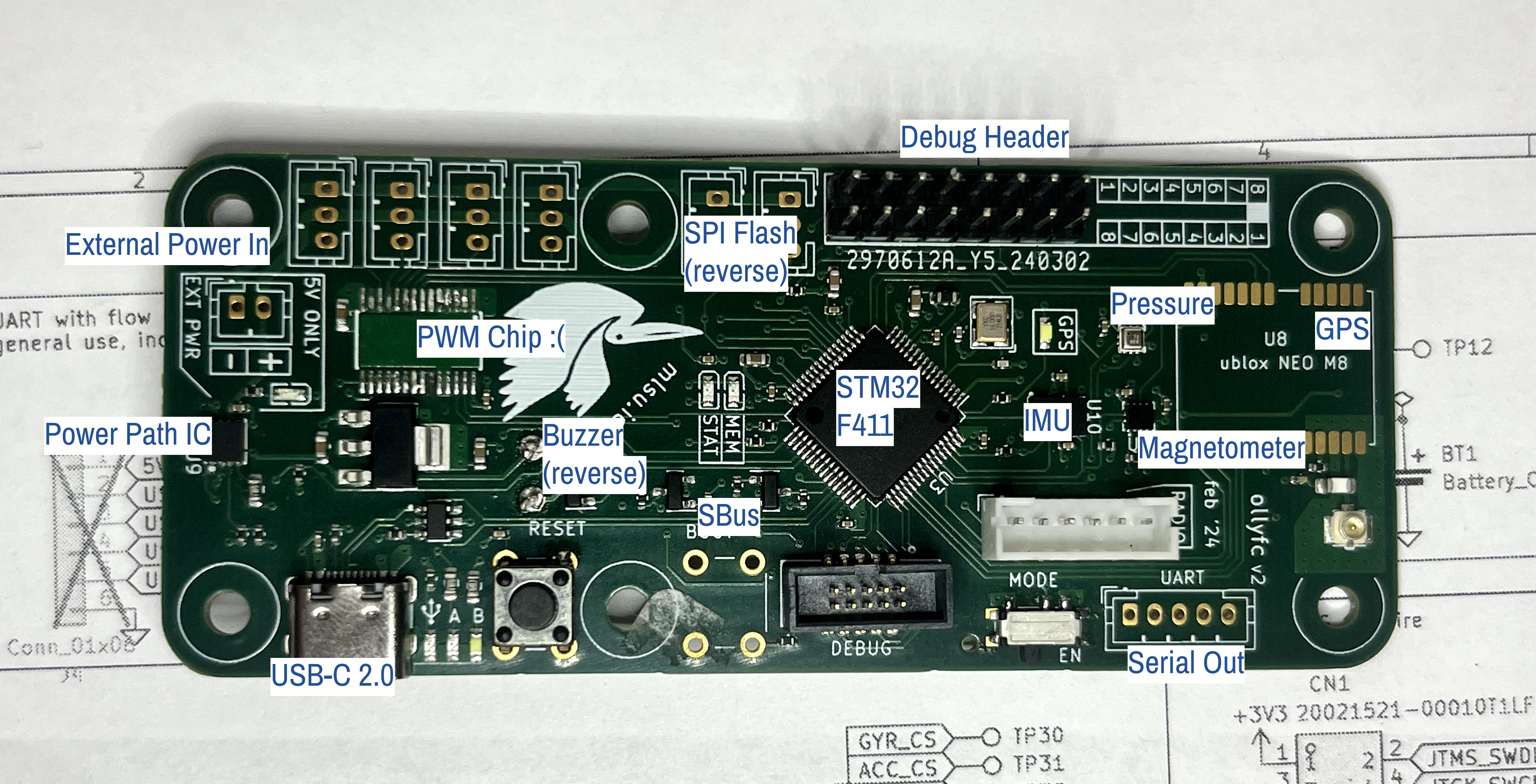
V2 Hardware
I found a number of other issues with the V1 board, so the v2 board was almost a complete redesign. The v2 board has a few differences:
- hand soldered SPI flash on the back, instead of on the front
- shrouded male debug port, instead of unshrouded
- More LEDs
- Eliminated the fuel gauge.
- Added GPS port with uFL antenna connector.
- Broke out UART pins onto connectors for additional IO.
- Test points on the rear
- Added a buzzer
And other various small component changes. The mechanical connection to the 30.5mm x 30.5mm drone PDB is retained.
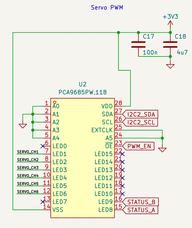
The PWM IC is the same, but the package changed to a cheaper and more available JLCPCB part.
Unfortunately, this board has a critical flaw: the PWM chip has a short across VDD and VSS. So I think what happens is that the current will flow e.g. through extclk, or A0-A5 to ground, instead of through VSS.
I knew I had a short, because I could feel the heat from the excess current flowing through the power path IC and the LDO, and eventually found that the component itself was heating up significantly.
This was pretty devastating, because it seemed like a $150 mistake and no additional progress could be made. However, because I opted to use an expensive power path IC, the current was limited which prevented major damage to the other components on the board.
Upon removing the offending IC, the chip powered on and could be flashed. None of the other components were affected. This was great news, becuase I could do bringup on some of the other components while I revised the board.
In hindsight, there were a number of issues with this board, too:
- PWM still not sufficiently isolated from the ST
- Used an expensive uncommon STM32F411 instead of an inexpensive STM32F401
- Used a u.FL antenna connector instead of a more common SMA
- All LEDs were reversed. This wasn’t strictly my fault, since I used footprints from EasyEDA but symbols from KiCad. They were reversed, so all of the LEDs were plugged in backwards on the board and hence none of them worked. Lesson learned: double check your footprints!
- The buzzer was also incorrectly connected: I had it on one of the negative complementary timer channels, instead of the positive channels. My HAL does not support having output on a complementary channel (and I’m not sure if this is true in general, or just with that particular HAL), so that meant no buzzer.
- RTC battery is quite small and an unknown type. And, no low speed crystal. I don’t want to be stuck buying hard-to-find batteries.
V3 Hardware
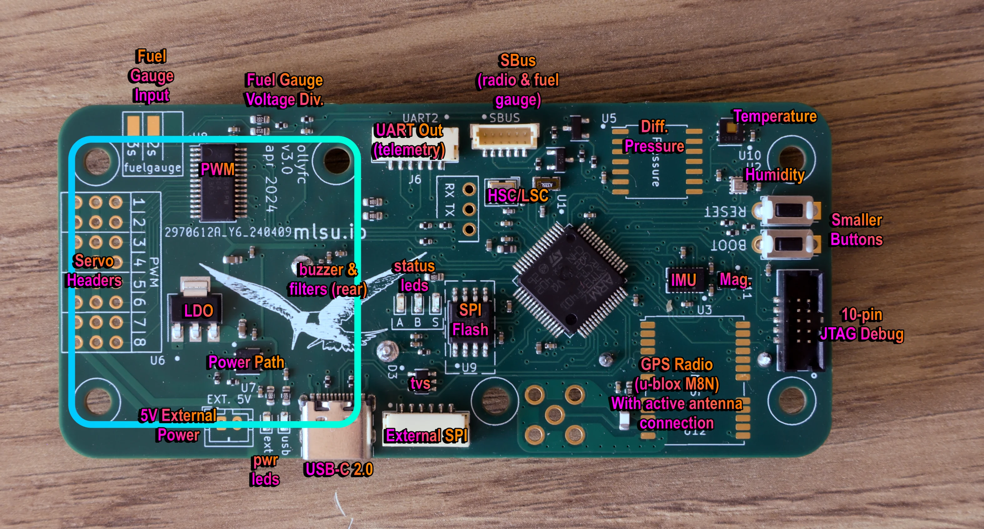
After the resounding success of the v2 silkscreen, I went with a significantly more intricate and complex logo for this board, based off of the California Least Tern which is native to San Diego.
This board is working well so far and is probably pretty close to the finalized product provided there are no bring-up issues.
This board has the following major components:
- MCU: STM32F401cb
- Differential Pressure Sensor: NPA-730B-10WD
- Temperature/Humidity Sensor: TI HDC1080
- IMU: Bosch Sensortec BMI088
- GPS: u-blox NEO M8N
- PWM: NXP PCA9685
- SPI Flash: Winbond W25Q128JVS
- Power Path: TI TPS2113ADRBR
The u-blox module and differential pressure sensor are both expensive, somewhat unnecessary, and large enough to be soldered on. So I did not have my assembly house do it, instead I am going to purchase those components and do the assembly myself.
A few things were changed on the v3 board:
- Larger buzzer. It has better acoustic properties. Unfortunately, it’s a little quiet (too much filtering), but it’s still audible at the resonant frequency of ~2800kHz.
- Larger battery. It’s a more common CR2032 type instead of the tiny batteries I had on the old board.
- Smaller buttons, which make it a lot easier to lay out the board.
- JST-GH connectors for the external SPI and the UART out. And, rather than placing them myself (like the old JST-PH connectors on the other board) I just had the assembly house do it.
- Likewise for the SBus connection. The FrSky radios have a JST-SH cable included so it is plug and play with the radio.
- Larger board made it much much easier to lay out. There is some “empty space” (corners, by the LDO, by the buzzer) but it’s still plenty compact enough and is a much cleaner layout.
- Isolation between the high-current parts and low-current parts of the board.The other two boards had a ground plane which extended under the entire board; this one has a gap next to the power path (where the 3v3 power comes in/out of the board from the LDO) I’m hoping this can diminish noise on the low-current portion, especially around the antenna.
- Fuel gauge inputs. I had ditched the fuel gauge IC from the v1 version, because the assembly house didn’t have it in stock, I didn’t do much paying attention to the details of integrating it so it was a bit half-baked, and I also don’t even NEED a fuel gauge IC, because the FrSky radio already has one – it’s just an analog input from the battery, through a divider, and into one of the SBus pins.
- 2.54mm headers for the servos instead of JST-PH connectors. The connector footprints took up a LOT of space, and it would have been a pain to crimp and connect each servo. I originally had connectors because of vibration, but I have noticed that most RC flight control boards with servos out have the 2.54mm connectors and seem to work just fine.
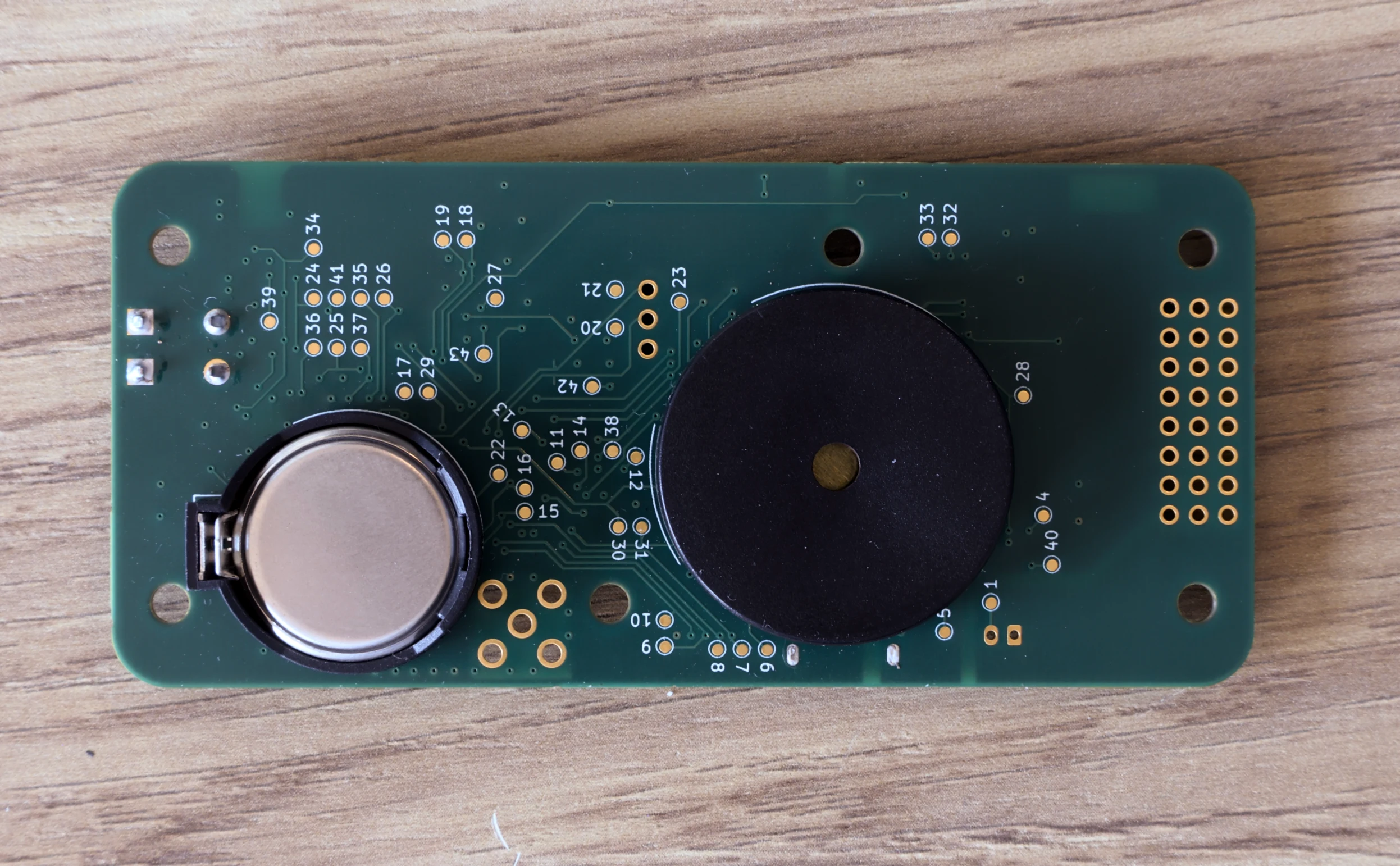
- Test points on the back of the board. Almost all signal lines, including interrupts, are broken out to test points. If this ends up being the final board design, I will probably manufacture a test harness with push pins to easily test the entire board. I have that bookmarked as a future hardware design project since if I ever put this into production testing will become part of the process.